FIRST
STEPS IN ‘O’ GAUGE.
Fifteen
year old Tom Lewis builds a Tower Collection Andrew Barclay 0-4-0ST beginners
kit.
Tom Lewis is fifteen and lives with his parents in the West Midlands. He was given a Hornby train set when he was six which he enjoyed for the next few years. Inevitably computers and video games became more attractive and the train set was discarded. This article tells of the rebirth of his interest and his successful first attempt at building an ‘O’ gauge locomotive.
My
Dad got interested in ‘O’ gauge about four years ago. Like me he had had a train set as a child and had retained some
interest. He started by building a few
Slaters and Parkside wagons and finally bought a Tower Collection Class 02
diesel shunter kit. This was supposed
to be a kit suitable for complete beginners and it must have been good because
he managed to build it without any problems.
He went on to build a couple more larger diesels and the house started
to fill up with ‘O’ gauge.
Finally
I decided to take up the hobby again.
Dad likes diesels but I don’t. I
wanted to build a locomotive but was only interested in steam outline. Given the high cost of kits (especially if
you are still at school!) I had to get it right first time.
Cheapest
option appeared to be a Mercian “Winnie” starter kit. Priced at £69.00 it seemed to be a bargain. To this has to be added wheels, gearbox,
motor and couplings bringing the total price up to about £142.00. My Dad took me to the ‘O’ gauge Guild event
at Chippenham and I was able to look at the kit. Although I liked the locomotive type the kit is mainly etched
brass with some whitemetal parts. It
would obviously require mainly solder construction and I wasn’t sure if I was
up to it. I decided to continue
looking.
A
friend of my fathers showed me a Springside Pug he had built. He told me the kit was supplied complete
with wheels, gears and motor and I could expect to pay around £175.00 for
it. It was useful to me being able to
examine the finished model. All the body
parts were made of cast whitemetal so could be glued instead of soldered. However it appeared rather complicated in
it’s construction so I decided against it. I then got chance to see other
models of similar price in the Springside range by looking at a website. I am told the Manning Wardle and the Coffee
Pot are both easier to build but I just didn’t like the prototypes.
The
next exhibition Dad was taking me to was the Association of Larger Scales
Railway Modellers event at Reading.
Prompted by my family I rang Tower Models and asked them if they were
attending and if they would have a sample of their Andrew Barclay beginners
kit. They said they would be there and
that they would have a built but unpainted sample of the locomotive on display
that I could handle.
A
week later at the exhibition I had chance to examine the finished item and to
go through the instructions of the kit.
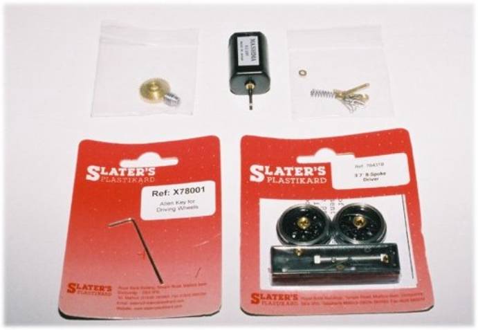
The instructions seemed very well detailed and I was impressed by the
completeness of the kit. It even
included the Allen key for fitting the wheels.
What is more, if it was as easy to build as the Class 02 diesel then it
should be no problem. After all, my Dad
had succeeded, so why shouldn’t I?
It
took all my birthday money from my parents and family to buy the kit which was
priced at £179.95. Dad told me I could
use his solder, soldering iron and glue so that would save me a few
pounds. I also knew I could rely on
help from his friends at the model railway club if necessary. I resisted the temptation to start it as soon
as I got home and waited until the following weekend before commencing building
work. I spent a few hours in the days
between to read the instructions and familiarise myself with all the parts.
The
following Saturday I decided to start work on the building. The kit came with twelve pages of
instructions including a number of exploded diagrams so I began by re-reading
them again. Tower Models had described
the kit to me as a screw and glue type kit that requires minimum amounts of
soldering. All the body parts could be
glued together with two part epoxy resin.
Only pickups, the wiring to the motor and a few small parts would need
to be soldered.
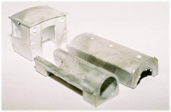
The
instructions suggest you start by building the body. The saddle tank is cast in one piece in pewter. Everyone tells me
this is better than whitemetal because it is stronger, melts at a much higher
temperature and contains less lead. The
saddle was cleaned up with a smooth file but was basically free from
flash. It was now necessary to drill the
holes for the handrail knobs. To be
more accurate, you have to deepen the holes using a 1.4mm drill. Dad let me use his Minicraft electric hobby
drill. I managed to deepen all eight
holes without breaking the drill bit.
The handrails can then be fitted in place. Dad told me it would be
better to solder the handrails in place but I fixed them with careful use of
superglue. The handrail wire was then
fitted through the knobs and again I used superglue to secure them. The chimney, water cover and whistle are now
ready to be glued in place using epoxy resin.
The
lower half of the boiler is also cast in one piece. The smokebox door handle needs to be fitted to the smokebox door
after deepening the hole with a 1.9mm drill.
The boiler, saddle and smokebox can now be all glued together, again
with epoxy resin.
The
cab is cast in one piece. A few small
parts have to be glued to it such as the brake handle and cover. The backhead is a separate piece and has to
be glued in place with the regulator fitted .
it was now necessary to fit the buffer beam to front and rear of the
footplate. I would have glued this but
an interfering father stated it was time to test my soldering skills. He argued that the buffer beams carry the
couplings and hence need to be securely fixed in place. Maybe he had a point but I was still a
little nervous.
Out
came the soldering iron, a liquid flux and some 70 degree melting point
solder. As Dad pointed out if I made a
mess of it I could drop the parts into boiling water and it would melt the
solder but not the parts. That was, as
he pointed out, providing I didn’t burn a hole in the metal, as was the fact I
was not allowed anywhere near Mum’s best pans should I make a mistake during the
soldering.
The
soldering iron was allowed to heat up, liquid flux applied to the parts, the
tip of the iron and the solder to be used.
I applied the iron to the solder, melted a bit onto the tip of the iron
and applied it to the joint between the bufferbeam and footplate.
Amazingly
it worked, it really was that simple. A
little more solder was applied to give the joint strength and then the buffer
beam at the other end of the footplate was soldered in place. Feeling more than a little pleased with
myself we took a coffee break.
Returning
to the job I then glued parts such as the tool boxes and reversing lever in
place. With the footplate completed it was laid aside. The handrails are now
fitted to the cab sides, following more drilling with a 0.7mm drill. The cab, assembled saddle and boiler all
screw fit onto the footplate. The
buffers, steps and couplings can now be fitted.
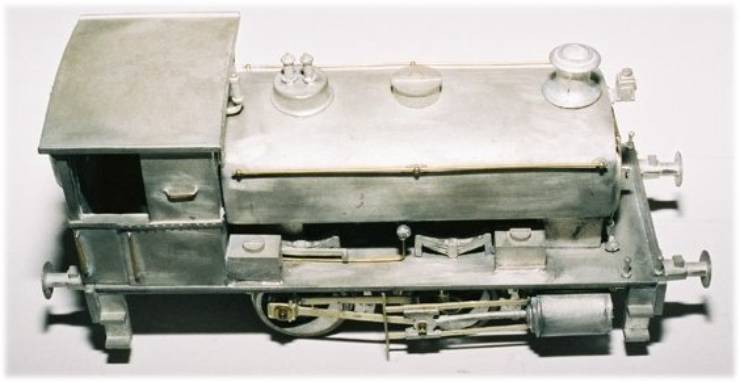
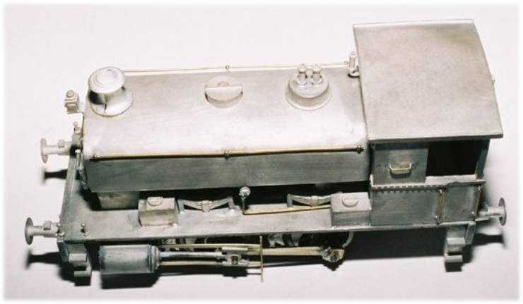
Four
hours after opening the box I had finished the body. I decided it would be better to quit while I was winning so I
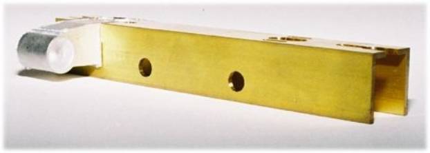
decided to leave the chassis until the following day. The chassis consists of a preformed heavy brass channel with all
the holes already drilled. The wheels
and axles supplied with the kit are Slaters.
The wheels are assembled on to one side of the axle, then passed through
the chassis and the other wheel fixed in place. A balance weight is then stuck onto the wheel. Crankpins, which are also supplied with the
wheels, need to be fitted before the wheels are fixed to the axles
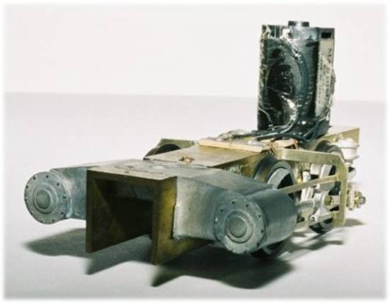
The
complete cylinder block is a casting. The cylinder end caps have to be fitted
in place and the whole assembly soldered to the chassis channel. As I was now soldering pewter to heavy brass
this was a first for me. Lots of heat, plenty of flux and crossed fingers all
must of helped because it worked. The
gear had already been fitted to the axle when the wheels were mounted to the
chassis. I left the grub screw loose so
I could settle the position of the gear once the motion was in place. Tower Models had told me to slightly
elongate the holes for the motor screws which would allow adjustment to the
fitting of the motor. A dry run,
fitting the motor in place with the screws and loose fitting the worm proved
this to be unnecessary. However, it was
a tip worth remembering.
The
grub screws were tightened on both the worm and gear and power supplied to the
motor just to give it a test spin. So
far so good, but next came the valvegear.
The valve gear was supplied in etched nickle, only the crosshead was a
pewter casting.
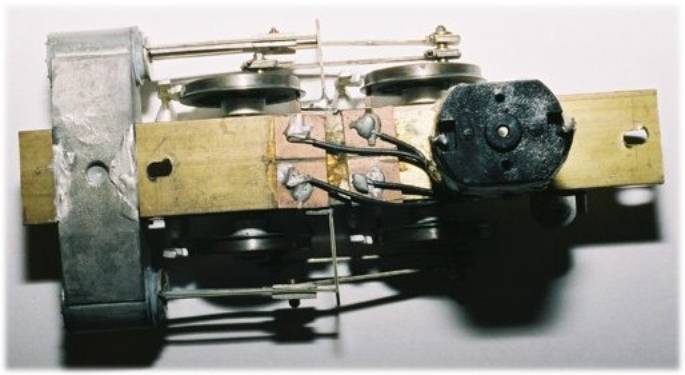
The
slide bars were so well designed they just folded up into shape. This was something I was dreading as I had
seen my fathers friends struggle with complicated valvegear on other kits. This all but fell into place, so much so I
had to double check the instructions to make sure I had not overlooked
something just to be sure. The
connecting and coupling rods were all fitted with the nuts supplied. The pickups had already been fitted in place
using low melt solder to secure them to the copperclad circuit boards. Wire could now be run through to the motor
and secured by low melt solder. The
time had come to test the locomotive.
To
my relief the locomotive ran fairly well straight away. A few very minor adjustments were made to
screws, nuts ad the pickups. A very
small amount of oil was applied to the worm and gear and the locomotive left
running against a block for twenty minutes to allow it to bed in.
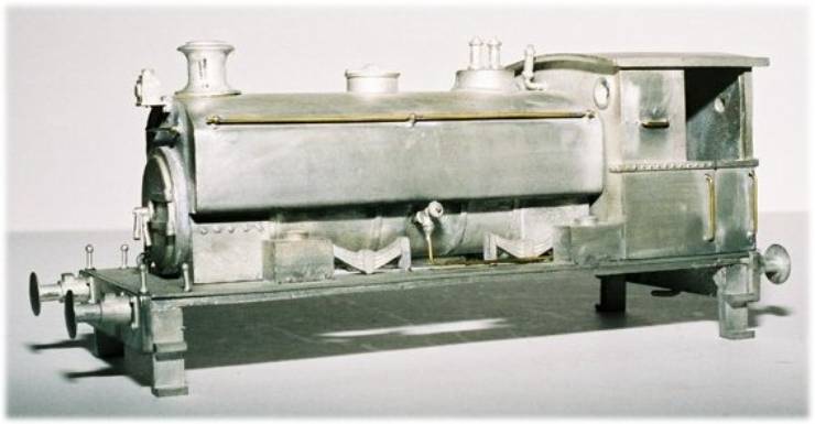
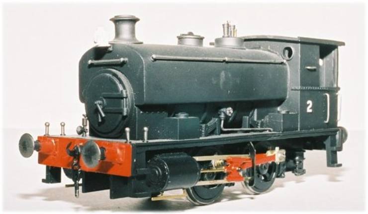
A
few nights later I was able to take it to the model railway club and give it
it’s first run. It was still unpainted
at this time but at least it worked. I have since painted the locomotive black
using car undercoat and matt black cellulose spray paint. It is necessary to remove the wheels to
paint the locomotive (unless you paint the chassis frames before assembly but I
didn’t think of that.)
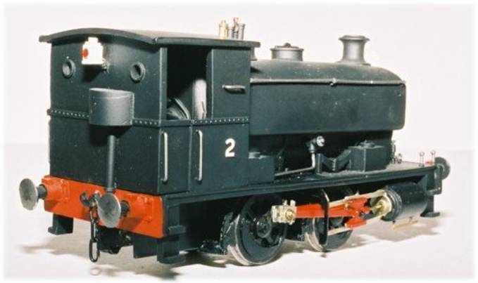
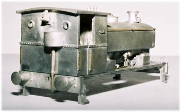
To
sum up I have enjoyed building this locomotive kit and am extremely pleased
with the result. An ‘O’ gauge
locomotive kit is not cheap and from what I have seen the quality varies from
one manufacturer to another. The kit I
bought was totally complete, well designed and truly simple to construct. I feel the finished item is something I can
be proud of. Obviously, due to
financial restraints (birthdays once per year and now eagerly awaiting
Christmas…) it will be some time before I can afford another kit but if it
works out as well as this one I will not be disappointed.
| Click Here to Return to the
|